


Chemical Fume Hood Working Principle – Complete Technical & Engineering Guide
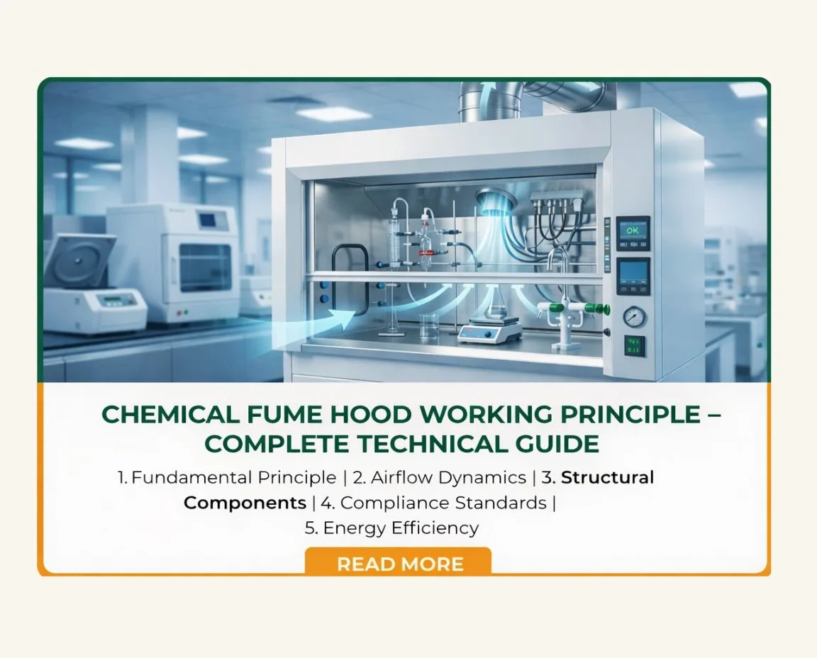
A chemical fume hood operates on the principle of controlled directional airflow and negative pressure containment to protect laboratory personnel from hazardous fumes, vapors, and airborne contaminants. By continuously drawing air inward through the sash opening and exhausting contaminated air safely away from the workspace, the system prevents toxic exposure and maintains laboratory air quality.
The effectiveness of this working principle depends on airflow engineering, structural design, exhaust balancing, compliance testing, and operational discipline. Understanding these technical foundations is essential for laboratory owners, safety officers, and procurement managers planning installation or system upgrades.
1. Fundamental Working Principle of a Chemical Fume Hood
1.1 Negative Pressure and Containment Mechanism
The core engineering concept behind a chemical fume hood is negative pressure. The air pressure inside the hood chamber is maintained slightly lower than the surrounding laboratory environment. This pressure differential ensures that air consistently flows inward rather than allowing hazardous vapors to escape outward.
When chemical reactions generate fumes, the inward airflow captures contaminants and directs them toward the rear exhaust system. This containment barrier at the sash plane protects the operator from exposure. Proper negative pressure balance is therefore essential to maintaining operator safety.
1.2 Directional Airflow Path Inside the Hood
Airflow follows a carefully engineered path inside the hood. Room air enters through the sash opening, moves across the work surface, travels through the rear baffle system, and exits via ductwork or filtration.
Below is a technical breakdown of the airflow sequence:
Airflow Sequence & Engineering Function
| Airflow Stage | Engineering Function | Design Dependency |
|---|---|---|
| Sash Entry | Initiates inward airflow | Sash height & face velocity |
| Airfoil Transition | Reduces turbulence at entry | Aerodynamic curvature |
| Work Surface Sweep | Captures vapors at source | Proper equipment placement |
| Rear Baffle Channeling | Eliminates stagnant zones | Multi-slot adjustable baffles |
| Exhaust Duct Exit | Removes contaminated air | Fan capacity & static pressure |
Each stage must function harmoniously for stable containment.
1.3 Role of Exhaust Systems in Maintaining Stability
The exhaust fan and ducting system maintain consistent airflow and pressure balance. Fan sizing must align with hood dimensions and laboratory HVAC integration. If exhaust capacity is too low, face velocity drops below safe limits. If excessively high, turbulence increases.
Laboratories planning installation should ensure that the selected Chemical Fume Hood is engineered with properly balanced exhaust systems to maintain stable negative pressure under real operating conditions.
2. Airflow Engineering & Face Velocity Dynamics
2.1 Recommended Face Velocity Standards (80–120 FPM)
Face velocity refers to the speed at which air enters the hood through the sash opening. Industry guidelines such as ASHRAE recommend maintaining face velocity between 80 and 120 feet per minute (fpm). This range ensures effective containment without creating airflow instability.
Face Velocity & Containment Performance Chart
| Face Velocity (FPM) | Containment Efficiency | Airflow Behavior | Risk Level |
|---|---|---|---|
| Below 60 FPM | Poor | Weak capture; fumes may escape | High |
| 60–80 FPM | Moderate | Sensitive to cross drafts | Moderate |
| 80–100 FPM | Optimal | Stable laminar flow | Low |
| 100–120 FPM | Controlled | Strong containment | Safe range |
| Above 150 FPM | Unstable | Turbulence & eddy currents | Reverse contamination risk |
Higher airflow does not always mean safer performance. Stability is more important than speed.
2.2 Turbulence, Eddy Currents & Boundary Layer Disruption
Excessive airflow velocity can create eddy currents inside the hood chamber. These vortices disturb the boundary layer separating contaminated air from the operator. Instead of smoothly moving toward the exhaust, vapors may circulate unpredictably. Engineering design focuses on minimizing turbulence through aerodynamic shaping and balanced airflow distribution.
2.3 Impact of Operator Behavior & Cross Drafts
External air currents from HVAC systems, open doors, or walking traffic can interfere with inward airflow. Rapid arm movement inside the hood may also disrupt containment stability. Strategic placement and operator training significantly enhance containment reliability.
3. Structural Components & Functional Design
3.1 Sash System & Airfoil Aerodynamics
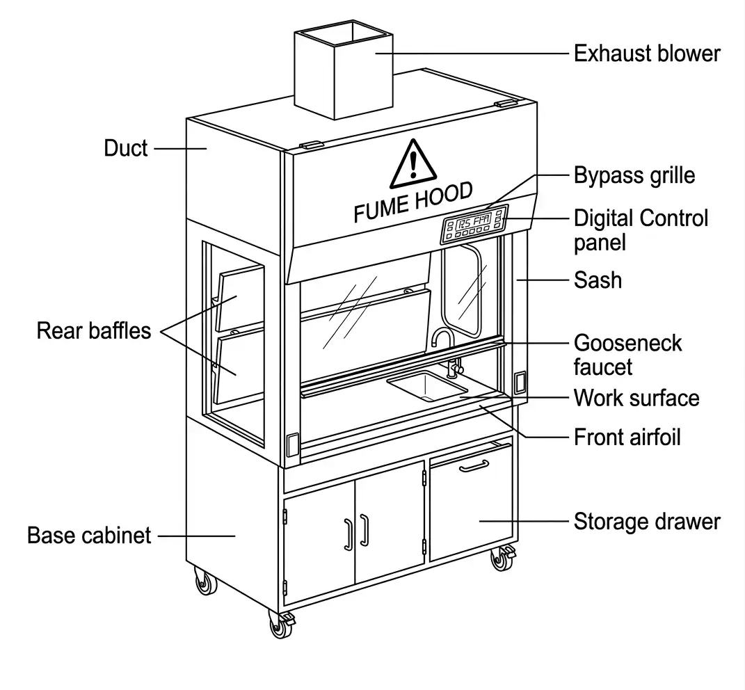
The sash acts as both a protective shield and airflow regulator. Lower sash height increases face velocity and enhances containment. Modern designs may include vertical or combination sashes for ergonomic and safety advantages. The airfoil smooths airflow entry, minimizing turbulence at the front opening.
3.2 Baffle Configuration & Dead Zone Elimination
The rear baffle system distributes airflow evenly across the hood interior. Adjustable slots allow balanced extraction from top, middle, and bottom sections. Without effective baffle engineering, stagnant zones can form, reducing extraction efficiency.
3.3 Work Surface Design & Equipment Placement Strategy
Work surfaces are constructed from chemical-resistant materials such as epoxy resin, stainless steel, or polypropylene. However, structural material alone does not ensure performance. Equipment should be elevated slightly to allow airflow beneath it.
Key Component & Functional Impact
| Component | Engineering Function | Impact on Containment |
|---|---|---|
| Sash | Controls opening size | Regulates face velocity |
| Airfoil | Smooths airflow entry | Reduces turbulence |
| Baffles | Direct airflow distribution | Prevents dead zones |
| Work Surface | Chemical resistance | Must allow airflow beneath equipment |
| Exhaust Fan | Maintains pressure | Ensures consistent containment |
For laboratories evaluating installation or upgrades, consulting experienced chemical fume hood manufacturers in Mumbai ensures structural and airflow design alignment.
4. Compliance Standards & Performance Validation
4.1 ASHRAE 110 Containment Testing Protocol
ASHRAE 110 evaluates containment performance using tracer gas testing. Sulfur hexafluoride (SF₆) is released inside the hood to simulate contaminant behavior.
ASHRAE 110 Performance Benchmarks
| Test Type | Condition | Acceptable Containment Level |
|---|---|---|
| As Manufactured (AM) | Factory condition | ≤ 0.05 ppm |
| As Installed (AI) | After installation | ≤ 0.05 ppm |
| As Used (AU) | Operational condition | ≤ 0.1 ppm |
These tests confirm that the hood performs according to its engineered working principle.
4.2 EN 14175 European Standard Requirements
EN 14175 includes airflow visualization, robustness testing, and containment measurement under cross-draft conditions. Compliance demonstrates reliability under real laboratory conditions.
4.3 Periodic Testing & Certification in India
Laboratories seeking accreditation under NABL or safety audits typically require annual airflow verification and containment testing. Selecting a compliant Chemical Fume Hood simplifies certification and long-term regulatory adherence.
5. Operational Efficiency, Failure Risks & Energy Optimization
5.1 Common Failure Modes in Laboratory Conditions
Containment may fail if airflow stability is compromised.
Laboratory Risk Assessment Matrix
| Failure Factor | Cause | Impact on Working Principle | Preventive Action |
|---|---|---|---|
| Thermal Loading | High heat equipment | Disrupts airflow direction | Limit heat load |
| Cross Drafts | HVAC or open doors | Pulls air outward | Strategic placement |
| Blocked Baffles | Improper setup | Dead zones form | Elevate equipment |
| High Sash Position | Operator error | Reduced face velocity | Sash discipline |
| Poor Exhaust Balance | Fan mismatch | Pressure instability | Commissioning calibration |
Routine inspection ensures sustained containment performance.
5.2 Ducted vs Ductless Performance Considerations
Ducted systems exhaust air externally, suitable for high chemical loads. Ductless systems rely on filtration and are limited by filter compatibility. Selection depends on application, compliance requirements, and laboratory infrastructure.
5.3 Energy Consumption & Variable Air Volume (VAV)
Ducted hoods continuously exhaust conditioned air, creating HVAC load. Variable Air Volume (VAV) systems adjust airflow based on sash height, reducing energy consumption.
Approximate Energy Impact of Ducted Hoods
| Hood Width | Average Airflow (CFM) | Relative Energy Impact |
|---|---|---|
| 4 ft | 700–900 | Moderate |
| 5 ft | 900–1200 | High |
| 6 ft | 1200–1500 | Very High |
Energy-efficient engineering enhances sustainability without compromising safety.
Frequently Asked Questions (FAQs)
What is the recommended face velocity for a chemical fume hood?
The recommended range is 80–120 FPM as per industry standards. This ensures stable containment without excessive turbulence.
How do I choose the right chemical fume hood for my laboratory?
Selection depends on chemical type, lab size, ducting availability, compliance requirements, and airflow capacity. Consulting experienced manufacturers ensures correct engineering alignment.
What standards should a chemical fume hood comply with in India?
Hoods should comply with ASHRAE 110 testing protocols and applicable safety guidelines. Laboratories seeking accreditation may require documented containment validation.
How often should a chemical fume hood be tested?
Annual performance testing is recommended to verify face velocity and containment efficiency. Ductless units require periodic filter inspection.
What factors affect the price of a chemical fume hood?
Pricing depends on size, material, airflow system type (CAV or VAV), ducting requirements, customization level, and installation complexity.

 Rj Lab Craft India PVT.LTD Survey No 35/2, Mandvi Village, Shirsad Vajreshwari
Road, Vasai, Virar (East) Maharashtra 401303
Rj Lab Craft India PVT.LTD Survey No 35/2, Mandvi Village, Shirsad Vajreshwari
Road, Vasai, Virar (East) Maharashtra 401303